How to determine the flow direction of a check valve?
Jun 03, 2025
Leave a message
Determining the flow direction of a check valve is a crucial aspect, especially for those involved in fluid control systems. As a seasoned check valve supplier, I understand the significance of accurately identifying the flow direction to ensure the proper functioning of these valves and the overall efficiency of the systems they are a part of. In this blog, I will share some effective methods and considerations for determining the flow direction of a check valve.
Understanding the Basics of Check Valves
Before delving into the methods of determining flow direction, it's essential to have a basic understanding of how check valves work. A check valve is a type of valve that allows fluid to flow in only one direction. It prevents backflow, which can cause damage to equipment, disrupt processes, and lead to safety hazards. There are various types of check valves, including swing check valves, lift check valves, and ball check valves, each with its own unique design and operating principle.
Physical Indicators on the Check Valve
One of the most straightforward ways to determine the flow direction of a check valve is by looking for physical indicators on the valve itself. Many check valves are marked with an arrow or other symbols indicating the intended flow direction. These markings are typically engraved or painted on the valve body, making them easy to spot. For example, our Grade 125 Cast Iron Check Valve comes with clear flow direction markings, ensuring that installers can quickly and accurately identify the correct orientation.
In addition to arrows, some check valves may have other physical features that indicate the flow direction. For instance, swing check valves often have a hinge on one side, and the valve disc swings open in the direction of flow. By examining the hinge and the movement of the disc, you can determine the correct flow path. Similarly, lift check valves have a disc that lifts off its seat to allow flow, and the direction of lift corresponds to the flow direction.
Valve Design and Construction
The design and construction of a check valve can also provide clues about its flow direction. For example, some check valves have a tapered or contoured inlet and outlet. The inlet is usually the side with the larger opening or the more gradual taper, as this allows for smoother entry of the fluid into the valve. On the other hand, the outlet may have a smaller opening or a more abrupt transition to help control the flow rate and prevent backflow.
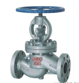
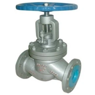
Another design feature to consider is the presence of a guide or seat arrangement. In some check valves, the disc is guided along a specific path to ensure proper alignment and sealing. The direction of the guide or the orientation of the seat can indicate the flow direction. For instance, in a Globe Check Valve, the disc moves in a linear path within the valve body, and the flow typically enters through the bottom and exits through the top.
System Requirements and Piping Layout
The overall system requirements and piping layout can also play a role in determining the flow direction of a check valve. In a well-designed piping system, the flow direction is usually planned in advance to optimize the performance of the entire system. Therefore, by referring to the system schematic or piping diagram, you can determine the intended flow path and ensure that the check valve is installed in the correct orientation.
For example, if the system requires the check valve to prevent backflow from a downstream pump or equipment, the valve should be installed with the inlet facing the source of the potential backflow and the outlet facing the direction of normal flow. Additionally, the piping layout may include other components, such as pumps, filters, or meters, which can affect the flow direction and the placement of the check valve. By considering these factors, you can ensure that the check valve is integrated seamlessly into the system.
Testing and Verification
Once the check valve is installed, it's important to test and verify its proper operation and flow direction. This can be done through a variety of methods, depending on the type of system and the available equipment. One common method is to use a flow meter or pressure gauge to measure the flow rate and pressure before and after the check valve. If the valve is installed correctly, the flow rate should increase in the direction of the intended flow, and the pressure should remain stable or increase slightly.
Another way to test the check valve is to visually inspect the valve disc or other moving parts. With the system operating, observe the movement of the disc to ensure that it opens and closes properly in response to the flow. If the disc remains closed or fails to open fully, it may indicate a problem with the flow direction or the valve itself. In such cases, it may be necessary to adjust the valve or perform further troubleshooting to ensure its proper operation.
Considerations for Special Applications
In some special applications, such as high-pressure or high-temperature systems, there may be additional considerations for determining the flow direction of a check valve. For example, in high-pressure systems, the valve may need to be designed to withstand the higher forces and pressures, and the flow direction may need to be carefully optimized to prevent damage to the valve or the system. In such cases, it's important to consult with a qualified engineer or valve expert to ensure that the check valve is selected and installed correctly.
Similarly, in high-temperature applications, the materials used in the check valve may need to be able to withstand the elevated temperatures without losing their integrity. The flow direction may also affect the heat transfer and the thermal expansion of the valve components, which can impact the valve's performance and longevity. Therefore, it's crucial to consider these factors when determining the flow direction and selecting the appropriate check valve for the application.
Conclusion
Determining the flow direction of a check valve is a critical step in ensuring the proper functioning of fluid control systems. By following the methods and considerations outlined in this blog, you can accurately identify the flow direction of a check valve and ensure its correct installation and operation. Whether you're a professional installer, a system designer, or a maintenance technician, understanding the flow direction of check valves is essential for maintaining the efficiency, reliability, and safety of your systems.
If you have any questions or need further assistance with check valves or their installation, please feel free to contact us. As a leading check valve supplier, we have a wide range of high-quality check valves, including API Swing Check Valve, to meet your specific needs. We are committed to providing excellent customer service and technical support to help you find the right solutions for your applications.
References
- Valve Handbook, 4th Edition, by J. Paul Tullis
- ASME Boiler and Pressure Vessel Code, Section VIII, Division 1
- API Standards for Valves and Fittings
Send Inquiry